- 3D-DART user manual
- The user manual provides a step-by-step explanation of all settings available at every step of the DNA modeling process.
Example projects ready for download as well as pre-loaded web forms are used to better explain several of the core functions. - Table of contents
- General introduction
- The 3D-DART server generates 3D structural models of double stranded DNA in either A-form or B-form. The modeling process requires
a initial template base-pair(step) parameter file representing the 3D conformation of a DNA starting structure. This parameter file is
subsequently used in further modeling actions. The template parameter file can be built in three different ways:
- From a straight "canonical" model with a user-defined base-pair sequence. This uses the "fiber" module from the 3DNA software package to generate the canonical 3D model and subsequently the "find_pair" and "analyze" modules from the same software to obtain the base-pair(step) parameter file.
- From a user-uploaded base-pair(step) parameter file.
- From another template 3D structure of a DNA in PDB format. This structure is be analyzed using the "find_pair" and "analyze" modules from 3DNA to obtain the base-pair(step) parameter file.
- The six base-pair and six base-pair step parameters (Fig. 1) in the generated parameter file can almost completely describe the conformation of a double stranded nucleic acid structure. Lu et al have indeed demonstrated (using there program 3DNA) that rebuilding a double stranded nucleic acid structure using these parameters results in a near native structure. The only exceptions are local changes in the sugar and phosphate backbone conformations.
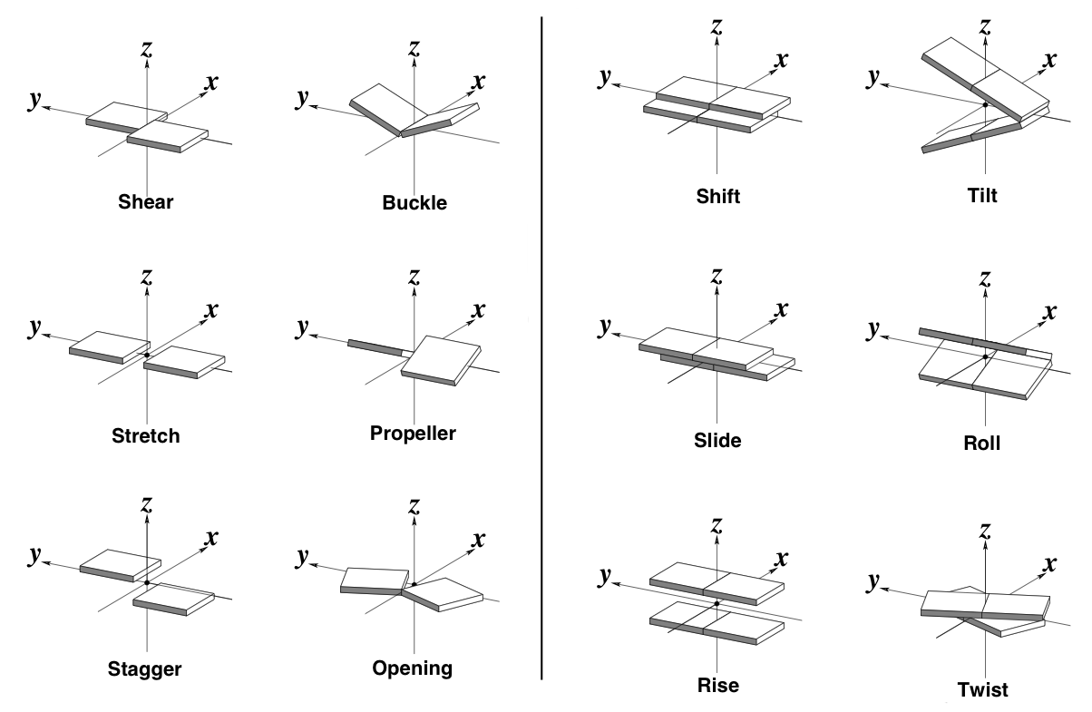
- Figure 1. The six base-pair (left) and base-pair step (right) parameters. Source: 3DNA website
- The 3D-DART web server makes use of these parameters to introduce custom changes in the structural models. Conformational modifications are divided into a global and local level. Modifications on a global level result in a bending, kinking and twisting behavior of the structure. These modifications are governed by the base-pair step parameters. Base-pair parameters operate on a local level and do not influence the global structure during the modeling procedure.
A bend angle in a base-pair step has two values associated with it: the magnitude of the angle and its direction in Euler-angle space. The origin in the Euler-angle space is set at a user-defined reference base-pair. The direction of a bend in an arbitrary base-pair is calculated relative to the reference base-pair.
The base-pair parameters Tilt, Roll and Twist are ideal for creating the bend. Both Roll and Tilt allow one base-pair to be tilted relative to another. Roll generates the most pronounced bend. The direction of the bend in Euler-angle space caused by Roll is positioned 90° to the plane in which the tilt generates a bend. By combining Roll and Tilt we can span 360°. Because the double stranded nucleic aid is twisted, we need to correct the direction of the introduced bend angle for the value of Twist. The "Custom Build tool" allows the user to define the magnitude of the bend, its direction relative to the reference base-pair and the range of base-pairs over which to bend. If the range is large, this results in a smooth bend; if the range is small, this results in a kink. The user can generate a single model with a fixed bend angle and direction or a set of models by defining minimum and maximum values for the angle and direction as well as a sample interval. Total control can be achieved by supplying a custom set of angle and direction values for every individual base-pair step in a given range.
Additional fine-tuning of the structures at a local level can be done by providing custom values for the remaining 6 base-pair and 4 base-pair step parameters. You will be able to define one fixed value that will be used for every base-pair and base-pair step in the sequence. If you wish to vary the value at give base-pair steps you can upload your own version of the base-pair (step) parameter file that will be used for modeling. Alternatively you can upload another DNA structure, in PDB format, that will be used a starting model for the introduction of additional conformational changes.- The 3D models generated by 3D-DART can be used as starting structures for the macro-molecular docking program HADDOCK also developed in our group. The successful use of DNA in this program requires the structure file to have a fixed layout and an accompanying DNA-specific restraints file that defines several restraints to preserve the helical structure of the DNA during the docking process. If you make use of the HADDOCK server to do your docking than this will all be done automatically. For users that operate HADDOCK locally on their own computational infrastructure the 3D-DART server offers the additional option to properly format the PDB files of the generated models and generate a restraint file for them.

- Please NOTE: the global nucleic acid conformations introduced using this server rely on strict geometrical principles. Depending on your settings they do not have to reflect a energetically favorable conformation. For example: you can introduce a 90° bend between two base-pairs in a sequence. Visual inspection of the structure will however immediately show you that the sugar-phosphate backbone is broken in half.
- Step 1. Build Nucleic Acid structures
- The first step in the modeling process involves the definition of the source for the template base-pair(step) parameter file and the type of DNA used in modeling
- Give your structure a name: The name you provide here will be used for all generated structure or structure-related files. If no name is provided the default name "dna" or the name of the uploaded base-pair(step) parameter file will be used.
- Define the nucleic acid sequence (5'->3'): Enter the desired nucleic acid sequence using a one-letter notation for the bases (A,T,C and G). Both small case and capital letters are accepted. Non-supported base notations and white spaces will be ignored. The sequence will serve as the template strand in the 5'-3' direction.
- Number of repeats: State how many times you would like the defined sequence to be repeated. The default is 1
- Build from user defined parameter file:
If desired you can build models from a predefined base-pair(step) parameter file. De DNA structure will be rebuilt according to the
specification in this parameter file. Modifications that you make afterwards, like the introduction of a bend, will be introduced in the
structure in a non-destructive manner. That is, only the base-pair step parameter necessary to introduce the bend will be changed while all
other parameters will remain the same as in the uploaded parameter file.
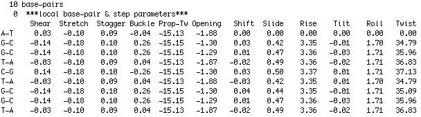
The base-pair(step) parameter file is in a format as used by 3DNA. Figure 2 illustrates the layout of the parameter file. The first row indicates the total number of base-pairs in the structure. The third row indicates the 6 base-pair and 6 base-pair step parameters respectively. The following rows indicate the base-pair (1th column) and the values for the base-pair and base-pair step parameters. By convention the very first base-pair does not have a corresponding base-pair step associated to it and therefore the base-pair step parameters all bear the value 0.00. You can download an example file here for you to edit and experiment with. Figure 2. 3DNA style base-pair step parameter file - Build from PDB structure file You can upload a PDB structure file of a dsDNA containing system. The DNA in the system is analyzed and a base-pair(step) parameter file describing the conformation of the DNA is generated. This parameter file will subsequently serve as a starting point for the model generation procedure
- Nucleic acid type: Choose the type of double stranded nucleic acid you would like to build. Options are: BDNA, ADNA and NDB96. The NDB96 set includes base and C1´ atoms, without sugar-phosphate backbone. ADNA set uses C3´ -endo sugar-backbone conformation as defined by Leslie et al. (1980) fiber studies, but with a χ torsion angle of -157°, average of high resolution single crystal X-ray oligonucleotide structures. BDNA set is similarly defined as ADNA except for a C3´ -endo sugar fiber sugar-backbone conformation and the -108° χ torsion angle.
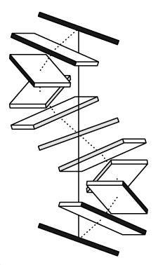
- Building models as a Calladine-Drew plot: The Calladine-Drew style representation of nucleic acid structures uses a block representation of base-pairs. This representation provides a clear view on the effects of base-pair and base-pair step parameters on the conformation of your structure. The representation is generated in ALCHEMY format and results in files having the suffix .alc and must be viewed in a ALCHEMY capable molecule viewer such as RasMol. You can choose to generate your ALCHEMY models using either the one block per base-pair or two blocks per base-pair option. You can generate Calladine-Drew plots together with structures in atomic representation in the same run.
- Figure 3. Calladine-Drew plot
- Step 2. Nucleic acids modeling options
- In step 2 of the modeling process you are able to introduce custom bend angles and custom values for the base-pair(step) parameters into the structure generated in step 1. The introduction of a bend involves setting up-to 3 parameters:
-
- The bend angle: Defines the magnitude of the bend angle in degrees between every successive base-pair. If nothing is set nothing will be changed.
- The bend orientation: Defines the direction of the bend angle in degrees between every successive base-pair. If nothing is set a default orientation angle of 45° is used
- The bend zone: the range of base-pairs for which the bend angle and/or orientation needs to be changed. If nothing is set the full sequence is used
- The way you need to define values in order to obtain the desired result depends on the modeling mode (global or local). A
full description of the settings with examples is given below.
- Modelling mode: By default this options is set to "global" meaning that the defined bend angle will be distributed evenly over the defined zone. By switching the modelling mode to "local" the user can set the bend angle and/or the bend angle orientation on a per base-pair step basis.
- Define bend angle range: This parameter defines the magnitude of the bend angle in degrees between every successive base-pair. If nothing is set than nothing is changed. The allowed values for this parameter depend on the modelling mode:
- Global: The defined bend is evenly distributed over the sequence. Defining one bend value will bend the sequence in the defined zone by the set angle. A angle range can be defined as "10-30". In this case multiple models will be generated within the range from 10° to 30° with a step size as defined in "bend-angle step size".
- Local: The defined bend angles are specific for a given base-pair step. If you specify a custom angle for every base-pair step in the sequence you do not need to set a zone. If you specify a custom set of angles for a specific region in the sequence you need to specify this region in the "bend zone" field.
- Define bend-angle step size: This defines the step size with which an angle range is sampled. This option can only be set if working in the "Global" modeling mode. If nothing is set a default of 1 will be used
- Define bend zone: Defines the base-pair range in which a given bend is introduced. The syntax is for example "5-10" where 5 is the start base-pair and 10 the end base-pair. If nothing is set the full sequence will be defined as bend zone. The syntax is the same for both modeling modes. However, be careful in the "Local" mode since every base-pair in the zone needs to be associated with a custom bend angle and/or bend angle orientation value.
- Define bend angle orientation range: This parameter defines the orientation of the bend angle in degrees relative to the reference frame between every successive base-pair. The allowed values for this parameter depend on the modelling mode:
- Global: Defining one bend angle orientation value will apply that value to every angle as defined in the "Define bend angle range" field. A orientation range can be defined as "10-30". In this case multiple models will be generated within the range from 10° to 30° with a step size as defined in "bend-angle orientation step size".
- Local: The defined bend angle orientations are specific for a given base-pair step. If you specify a custom orientation for every base-pair step in the sequence you do not need to set a zone. If you specify a custom set of orientations for a specific region in the sequence you need to specify this region in the "bend zone" field.
- Define bend angle orientation step size: This defines the step size by which an angle range orientation is sampled. This option can only be set if working in the "Global" modeling mode.
- Base-pair used as origin in global reference frame: This defines the origin of the global reference frame used for calculating the bend angle magnitude and orientation. Definition of this parameter is optional, by default the middle base-pair of the zone is used.
- Define the helical phase: This defines the number of base-pairs in one helical turn by changing the Twist value for every base-pair step. If no value is defined a default of 10 bp/turn will be used. If you define a custom Twist value to be used for modelling, than this will override the helical phasing.
- Use custom defined values for base-pair and base-pair step parameters: If you wish to use other values for the base-pair and base-pair step parameters than those defined by default you can set them in the appropriate boxes. All the values for the given parameter will be set to this new custom value. Other values will not be affected.
- A few examples illustrating the various options:
Example 1:
A bend angle of 60° in a 20 nucleotide BDNA sequence will introduce a 3° bend angle between every successive base-pair. The resulting structure will therefore be evenly bent. The orientation of every angle in Euler-Angle space is not set and will default to 45° throughout the sequence.
View model Download results Pre-loaded web form Example 2:
A bend angle of 30°, in the same structure as example 1, spanning a zone of 3 nucleotides from base-pair 9 to 12, will introduce a 10° bend between base-pair 9-10, 10-11, 11-12 and 12-13. This will kink the structure in the center. The orientation of every angle in Euler-Angle space is not set and will default to 45° throughout the sequence.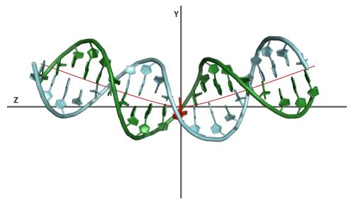
View model Download results Pre-loaded web form Example 3:
Again a 60° bend in the structure of example 1. This time however we will change the orientation of the bend in Euler-Angle space. To illustrate the effect we generate multiple models spanning a range from 0-90 ° with steps of 45°. This will generate bent structure with an orientation of 0°, 45° and 90° relative to the reference base-pair.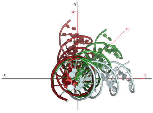
View model Download results Pre-loaded web form Example 4:
An example of modelling using the Local mode. BDNA model generated with a custom sequence of bend angles and associated orientation. The bend angle sequence was: 2,2,3,3,6,6,3,3,2,1,1,2,3,3,6,6,3,3,2,2 the orientation sequence was: 90,80,70,60,50,40,30,20,10,0,180,190,200,210,220,230,240,250,260,270.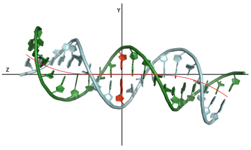
View model Download results Pre-loaded web form Example 5:
This example illustrates the use of a base-pair(step) parameter as start point for modelling. The parameter file representing the conformation of the DNA in the intron-encoded endonuclease I-PPOI/DNA complex (PDB-id:1A73) is used as input. The DNA in this complex is heavily kinked in the center. Using the server we will generate a set of models of this structure all having a different bend angle in the center. The settings: modelling mode is set to "Global", a bend angle range of 10-50, stepsize of 10, default orientation and a bend zone of 8-14. Using the "view model" link you can view the original heavily kinked structure of the DNA in complex and one of the models having a kink of 10°. This example illustrates that the server is capable of making changes to a specific region of the DNA while preserving the conformation of the remaining part of the structure.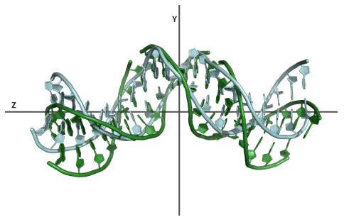
View Model Download results Download parameter file
- Step 3. PDB formating options
- PDB formating options are optional but useful if you have special wishes concerning the output format of your 3D coordinates files. These options and a few additional ones are also used in step 4 for preparing the structural models for use in HADDOCK
- Convert IUPAC to CNS notation: If you wish to use the generated PDB files in the structure calculation program CNS than this option will convert the IUPAC atom notation to there CNS equivalents. The following atoms notations are converted:
-
- In case atoms of the sugar-phosphate backbone contain a "*" notation (e.g. C4*) or (**) in case of some hydrogen's these are converted to (') or ('') notation.
- The Thymine C5M atom notation is converted to C7.
- Convert nucleic acid 1 letter to 3 letter notation: By default the nucleic acid residues are presented in a one letter notation. You can have this changed to a three letter notation
- Set PDB chain ID: By default the first chain in the double stranded nucleic acid is identified by "A" and the second by "B". If you use the "Prepare for use in HADDOCK" option as described below the chain ID of both chains will be set to "B". The "Set chain ID" option gives you the ability to convert the chain ID to a new value.
- Renumber residues starting from: You can have the residue numbering starting from a defined number
- Step 4. For HADDOCK users
- Prepare PDB files for use in HADDOCK: The default PDB format generated by the "rebuild" tool of 3DNA is not suitable for use in HADDOCK. This option performs the necessary modifications. It combines several of the PDB formating options together with a few new ones in one command. The following changes are made:
-
- Add a "END" statement to the end of the PDB file.
- Remove the SEGIDs if present (the SEGID is a four character long string at columns 73-76 in the PDB format. This is particularly important for docking from an ensemble of starting conformations. If not blanked, the topology and structure generation step will give problems.
- Convert nucleic acid one-letter code to there equivalent three-letter code.
- Convert the IUPAC atom notation to the CNS atom notation
- Convert the Thymine C5M atom notation to C7.
- Renumber all atoms starting from 1. Use the "Renumber residues starting from" options to change to another value
- A nucleic acid is treated as one segment by default in HADDOCK. A segment must have one unique segment (or chain) ID. The "prepare for use in HADDOCK" formatting option defines the segment ID as "B" by default. Use the "Set PDB chain ID" options to change to another segment ID
- DNA/RNA restraints file: When using double stranded nucleic acids in HADDOCK an additional set of restraints is required to maintain the helical conformation of the structure. This file, always called dna-rna_restraints.def, defines the following restraints:
-
- Watson-Crick base-pair planarity restraints
- Ring planarity restraints for the bases
- Watson-Crick hydrogen bond restraints
- Ribose sugar pucker restraints
- Sugar-phosphate backbone dihedral angles restraints
- When you use this option, the restraint file will be automatically generated based on the DNA models you created. Since this restraint file
is intended for use in HADDOCK, the DNA models will be formated for correct use in HADDOCK (the option "Prepare PDB files for use in HADDOCK"
will be checked)
Their are a number of settings in the dna-rna_restraints.def file that you can define in the web-form. - Planarity restraints
- The planarity of the individual base rings is restrained by default. Optionally you can restrain the two bases of a Watson-Crick base-pair to be in the same plane. The flexibility of the system in the flexible phase of the docking will be reduced significantly when this option is checked. Alternatively, one can use Watson-Crick base-pair restraint to restrain the length of the Watson-Crick hydrogen bonds. With this, the bases in a pair can still move relative to one another without unpairing.
- Watson-Crick base-pair restraints
- This option restrains the length of the Watson-Crick hydrogen bonds between the defined upper and lower bounds. With the individual bases of a base-pair are still able to move relative to on another without unpairing.
- Set sugar-pucker dihedral angle restraints
- Sugar-pucker dihedral angles are restrained during the docking. The values for the dihedral angles (as shown in table 1) and the error range within which the value is restrained can be defined. The value of the dihedral angle restraints can be defined in four different ways:
-
- "Pick the dihedral angles of the sugar pucker from the input structure " This is the default option. It measures the dihedral angles from the input structure(s) and restrain them within a default error range as shown in table 1. You must define the groups of residues for which you wish to setup the restraints. You can define up-to 3 groups. Within each group you have to define the start and end residue
- The dihedral angles can be restrained to match the average values of standard B-form DNA (see table 1). To use this option set the conformation of each defined group to "B-form"
- The dihedral angles can be restrained to match the average values of standard A-form DNA (see table 1). To use this option set the conformation of each defined group to "A-form"
- You can define custom values for the sugar pucker dihedral angle by setting the conformation of each group to "User defined" and specifying the value of the custom dihedral angle and its error range
- Option 1 is set by default and preferred if you want to ensure a dynamical behavior of your nucleic acid during the docking. The restraint file is used in both the semi-flexible torsion angle dynamics refinement stage and in the final water refinement. If option 1 is used the angles of the input structures are measured and restrained at the start of both stages. This allows for more conformational freedom of the nucleic acid backbone during the docking. If any other option is used, the dihedral angles are restrained around fixed values and the conformational freedom will be reduced.
- Table 1. Default values for sugar-pucker dihedral angles and their error range (degrees) in A-form and B-form DNA
- Sugar-phosphate backbone dihedral angles restraints
- Sugar-phosphate dihedral angles are restrained during the docking. The values for the dihedral angles (as shown in table 2) and the error range within which the value is restrained can be defined. The value of the dihedral angle restraints can be defined in the same four different ways as for the sugar-pucker dihedral angle restraints.
- Table 2. Default values for sugar-phosphate dihedral angles and their error range (degrees) in A-form and B-form DNA
| Dihedral angle | B-form | A-form |
| C1′-C2′-C3′-C4′ | -34.9 +/- 0.0 | 37.053 +/- 0.0 |
| C5′-C4′-C3′-C2′ | -86.4 +/- 0.0 | -155.59 +/- 0.0 |
| C1′-O4′-C4′-C5′ | 106.4 +/- 0.0 | 144.26 +/- 0.0 |
| Dihedral angle | B-form | A-form |
| Aplha O3′-P-O5′-C5′ | -63.6 +/- 6.0 | -70.0 +/- 50.0 |
| Beta P-O5′-C5′-C4′ | 176.0 +/- 7.0 | 180.0 +/- 50.0 |
| Gamma O5′-C5′-C4′-C3′ | 51.4 +/- 7.0 | 60.0 +/- 35.0 |
| Delta C5′-C4′-C3′-O3′ | 128.0 +/- 13.0 | 81.0 +/- 20.0 |
| Epsilon C4′-C3′-O3′-P | -171.7 +/- 3.7 | 180.0 +/- 35.0 |
| Zeta C3′-O3′-P-O5′ | -103.8 +/- 4.0 | -85.0 +/- 50.0 |
- Web server output
- The final output of the server is produced by executing several separate modules. The output of every module is saved into a separate directory. At the end of the program execution all directories are combined into a zip archive and presented for download. For an average run you can expect to find the following directories and their content in the zipped archive:
-
- 1. FileSelector: whenever you start the modeling process from a base-pair step parameter file or PDB structure you will find these files in this directory.
- 2. BuildNucleicAcid: if you start the modeling from a sequence or parameter file than this directory contains the (canonical) DNA structure representing the input. If you start from a PDB structure this directory remains empty.
- 3. X3DNAanalyze: if you started the modeling process from a sequence or a PDB file this module will generate the base-pair(step) parameter file describing the conformation of the structure. If you started from a base-pair(step) parameter file this directory remains empty.
- 4. ModelNucleicAcids: This is where all the magic happens. This directory contains all the base-pair(step) parameter files representing the various 3D structural models you decided to create.
- 5. BuildNucleicAcid: This directory contains the PDB coordinates files generated from all base-pair(step) parameters in the previous directory.
- 6. X3DNAanalyze: This directory contains the 3DNA analysis output generated for all models in the previous set. For an explanation of the content of the various files in this directory please consult the 3DNA user manual
- 7. NABendAnalyze: This directory contains the nucleic acid bend analysis files giving you insight into the distribution of bend angles in the generated models. An example with explanations is provided here
- 8. PDBeditor: Any custom modification to the PDB structure files will be put in this directory. These are for instance: residue renumbering, chain ID definition or preparation for use in HADDOCK.
- 9. NArestraint: This directory will contain the dna-rna_restraints.def file for use in HADDOCK if the option was used. If not this directory will not be present.
- You can obtain examples of server output from the examples described earlier in this manual or from our 3D-DART gallery
- Frequently asked questions
- How can I cite 3D-DART?
- M. van Dijk and A.M.J.J. Bonvin (2009) "3D-DART: a DNA structure modelling server",Nucl. Acids Res., 37 (Web Server Issue):W235-W239 doi:10.1093/nar/gkp287
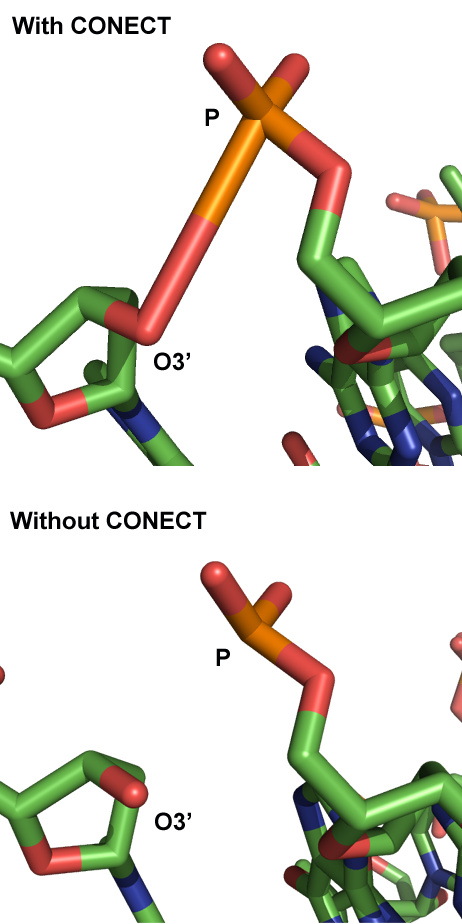
- Some P-O3' bonds in the sugar-phosphate backbone of bend structures seem to be longer than physically possible. What is going on?
- The 3D-DART server calculates how the base-pairs in the sequence are supposed to be oriented relative to one another to result in the user-defined global conformation like a kink or bend. The "rebuild" module of 3DNA then uses this information to position the atomic coordinates of the different nucleotides to generate the actual structure. The calculation however only considers the individual bases to modify the global conformation and not the sugar-phosphate backbone; as a consequence, the backbone will always remains in the same conformation. To link the nucleotides together via the P-O3' bond the "rebuild" module does not use an energy minimization procedure but instead writes a CONECT statement to the PDB file that will command a structure viewer to create the bond. This will give the impression that nucleotides are properly linked even if the distance between P-O3' is too long for an actual bond to occur.